Delphi 13.1 Florence, VCL, TMS FNC Core 4.5.0.0 (used with TMS FNC Gantt Chart 1.3.3.10).
Two issues in the PDF output of FNC Core. In both cases the PDF looks different from the screen and from a printout of the same drawing.
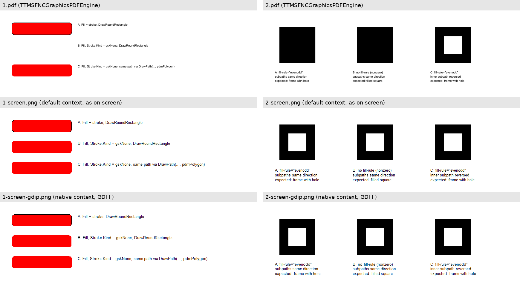
The attached demo draws each scene with one routine three times: into a PDF (TTMSFNCGraphicsPDFEngine), and on a TTMSFNCGraphics bitmap canvas with the default context and with the native context (GDI+). On start it runs both scenes once and writes 1.pdf / 1-screen.png / 1-screen-gdip.png and the same for 2, next to the exe. The buttons repeat it and show the scene in the window. The attached image shows the result.
1. TTMSFNCGraphicsPDFEngine.DrawRoundRectangle draws nothing when there is a fill but no stroke
VCL.TMSFNCGraphicsPDFEngine.pas, line 800 ff.:
if (Fill.Color <> gcNull) and (Fill.Kind <> gfkNone) then
begin
  if (Stroke.Kind <> gskNone) and (Stroke.Width <> 0) then
    DrawPath(pth, pdmPolygon)
  else
    DrawPath(pth, pdmPolyline)     // fill only -> DrawPolyline
end
else if (Stroke.Kind <> gskNone) and (Stroke.Width <> 0) then
  DrawPath(pth, pdmPolyline)
For a fill without a stroke, the path goes to DrawPolyline (line 771). That method only draws when a stroke is set, and only as a stroke. So a filled round rectangle without border produces no output at all: no fill operator in the content stream, no error. DrawPolygon (line 744) handles a fill with and without stroke correctly, so I think the inner else should use pdmPolygon as well.
Demo, scene 1, three red round rectangles:
- A: fill + stroke,
DrawRoundRectangle– screen and PDF: red - B: fill,
Stroke.Kind := gskNone,DrawRoundRectangle– screen: red, PDF: missing - C: fill, no stroke, the same path drawn with
DrawPath(..., pdmPolygon)– screen and PDF: red
How we found it: in our Gantt chart the open part of a task's progress is a pale, filled round rectangle without border. On screen and on paper it is there, in the PDF export it was missing. We now use the path of C when the target is a TTMSFNCGraphicsPDFEngine.
2. SVG fill-rule is ignored, and screen and PDF use different fill rules
VCL.TMSFNCGraphicsSVGEngine.pas does not read fill-rule. The SVG paths are drawn with pdmPath, and the result then depends on the target:
- Screen, default context:
TTMSFNCGraphicsContextGeneral.FillPath(VCL.TMSFNCGraphics.General.pas, line 2316) usesWindows.FillPath, i.e. the polygon fill mode of the DC. That is the defaultALTERNATE(even-odd);SetPolyFillModeis never called. - Screen, native context (GDI+):
TTMSFNCGraphicsContextWin.CreatePath(VCL.TMSFNCGraphics.Win.pas, line 816) creates theTGPGraphicsPathwithout a parameter, i.e.FillModeAlternate(even-odd). - PDF:
TTMSFNCGraphicsPDFEngine.DrawPath(line 641 ff.) always ends withdmPathFillordmPathFillStroke(f/B, nonzero), although the PDF library supportsdmPathEOFill(f*,VCL.TMSFNCPDFGraphicsLib.General.pas, line 851).
Demo, scene 2, three SVGs – an outer square with an inner square:
<path d="M10 10H90V90H10Z M30 30H70V70H30Z"/>
- A:
fill-rule="evenodd", both subpaths in the same direction. Expected: frame with hole. Screen: hole. PDF: filled. - B: no
fill-rule(SVG defaultnonzero), same path. Expected: filled square. Screen: hole. PDF: filled. - C:
fill-rule="evenodd", inner subpath reversed (M30 30V70H70V30Z). Expected: frame with hole. Screen and PDF: hole.
So the same SVG is filled differently on screen and in the PDF, and with the default rule the screen is the one that is wrong. Our case was a warning triangle (a triangular ring with "!"), drawn via <img src="...svg"> in a task list cell: correct on screen, a solid black triangle in the PDF.
Suggestion: read fill-rule (and clip-rule) in the SVG engine and pass it on: SetPolyFillMode / FillMode on screen, f* / B* in the PDF. At least screen and PDF should use the same rule. We now reverse the direction of inner subpaths in our icons, as in C, so both rules give the same result.
Thanks!
FNCCoreIssues.zip (6.8 KB)